| |
 Features
 |
|
|
| - |
Frequency measuring range : 0Hz to 120MHz (A input,
B input) 100MHz to 2.4GHz (C input) |
| - |
Full autorange, 7 digits display with
0.01mHz resolution |
| - |
Programmable Record (MAX / MIN) |
| - |
Programmable Relative (REF / ERR) |
| - |
Programmable Compare (GO-NOGO) |
| - |
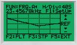
Trend Plot : REF is the centerline value
on the trend graph. H/Div is the X axis (time) and |
| |
V/Div is the Y axis (amplitude). |
| - |
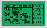
Setup : Setting and functions are selected
and stored in memory from the front panel. |
| |
Eight setups are stored in memory. |
| - |
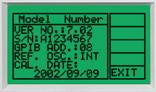
Equipment : Display information about
your instrument including model number, serial number,
|
| |
calibration date, GPIB address and firmware
revision. |
| - |
Remote Control : Built-in RS232C or optional GPIB
interface |
| - |
128 by 64 pixel super twisted LCD display |
| - |
Power Source : 85V to 270VAC (±10%, 48 to 66Hz) |
| |
|
 |
 |
 |
| Programmable Record |
Programmable Relative |
Programmable Compare |
| |
|
|
 |
 |
 |
| Trend Plot |
Setup |
quipment |
|
| |
Block Diagram |
|
|
| |
Specification |
|
|
|
CHA input Characteristics |
|
| Frequency Range |
|
| Sensitivity |
|
| Impedance |
|
| Attenuator |
|
| Max. Input voltage |
|
| Trigger level |
|
| Trigger slope |
|
| Resolution |
|
|
| 0 to 120MHz(DC Coupled), 10Hz to 120MHz(AC coupled) |
|
| 25mV RMS (Sine Wave) |
|
| 1Mohm less with less than 35pF capacitance |
|
| x1, x10 |
|
| 250V (DC or AC Peak) |
|
| ±1.28V variable. |
|
| Positive or Negative |
|
| 0.001Hz (G.T = 1 Sec. 200Hz) |
|
|
|
|
|
|
CHB input Characteristics |
|
Same as CHA |
|
Same as CHA |
|
|
|
|
|
|
Measurement Function
|
|
| (1)FRQ. A ? Range: 0 to 120MHz(DC Coupled),
10Hz to 120MHz(AC coupled) |
| - Coupling: AC or DC |
| - Slope: Positive or Negative |
| - Trigger level: ±1.28V variable |
| (The trigger level is displayed as a scale
?99 to +99 units) |
| - Low Pass filter: Approximately 100 |
| - Attenuation: 0 and 20dB (x1 and x10) |
| - Resolution: 0.00001Hz (Gate time = 1Sec,
Input Frq = 200Hz) |
| - Accuracy: ±Time Base Error ±1 Count |
|
|
| (2) FRQ.B: ? Same as FRQ. A |
|
| (3) FRQ.C: -Range: 100MHz to 2.4GHz |
| - Slope: Positive or Negative |
| - Trigger level: Auto |
| - Coupling: AC |
| - Accuracy: ±Time Base Error ±1 Count |
|
|
| (4)Time Interval (A→B): - Range: 0.5uS
to 0.2S (5Hz to 2MHz) |
| - Pulse width: 250nS minimum |
| - Resolution: 0.1uS Max |
| - Accuracy: Time Base Error ± CHA Trigger
Error ± Magnification ±1 Count |
|
|
| (5) TOT. A (Totalize): -Range: DC to 10MHz
|
| - Count Capacity: 0 to 9,999,999 (Over
Flow) |
| - Hold button controls the Start and Stop |
|
|
| (6) Ratio A/B - Range: CHA input: 10MHz
to120MHz, CHB input: 0.1MHz to 10MHz |
| - Accuracy: CHB Trigger Error/(CHB Freq.
x Gate Time) ±1 Count |
|
|
| (7) A-B Freq. Difference: - Frequency
Range: Same as CHA and CHB |
| - Accuracy: Time Base Error ±1 Count |
|
|
| (8) RPM A measure: - Maximum RPM: 600,000
RPM |
| - Minimum pulse width: 250nS |
|
|
|
|
|
|
|
GATE Times |
|
| - 50mS, 100mS, 200mS, 300mS, 400mS, 500mS, 600mS,
700mS, 800mS, |
| 900mS, 1S, 2S, 3S, 4S, 5S, 6S, 7S, 8S, 9S, 10S |
| - Gating Accuracy Time base accuracy: 1ppm |
|
|
|
|
|
|
| Reference Time |
| Base Oscillator |
| |
|
|
| - Standard Frequency: 10MHz, 4.194304MHz |
| - Frequency Stability: ±5.0ppm max |
| - Aging Rate: ±1.0ppm max./year |
| - Temperature: -30°C to +60°C |
| - Storage Temp. Range: -40°C to +85°C |
|
|
|
|
|
|
General |
|
| Power Source |
|
| Dimensions /Weight |
|
| Standard Accessories |
| |
|
| Optional Accessories |
|
|
| 85V to 270Vac(±10%, 48 to 66Hz) |
|
| 235(W) x 296(D) x 85(H) mm / About 1.5 kg |
|
| Users Manual, BNC cable (BNC & Clip), Line
Cord, |
| Spare fuse, RS232 Cable and S/W |
|
| GP-IB (IEEE-488.2) Interface (Installed) |
|
|
|
|
|
|
|